BS-1: Breadboard Synthesizer
September 3, 2021 - 9 minute read
While I mainly focus on the software side of computers, I have always had an interest in electrical engineering too. So, after getting burnt out over some programming projects, I decided to try out something a bit different and build some sort of electronic circuit. I took inspiration from all the breadboard computers people have built, mostly inspired by Ben Eater, but I decided to take a different approach and built an analog synthesizer on breadboards instead.
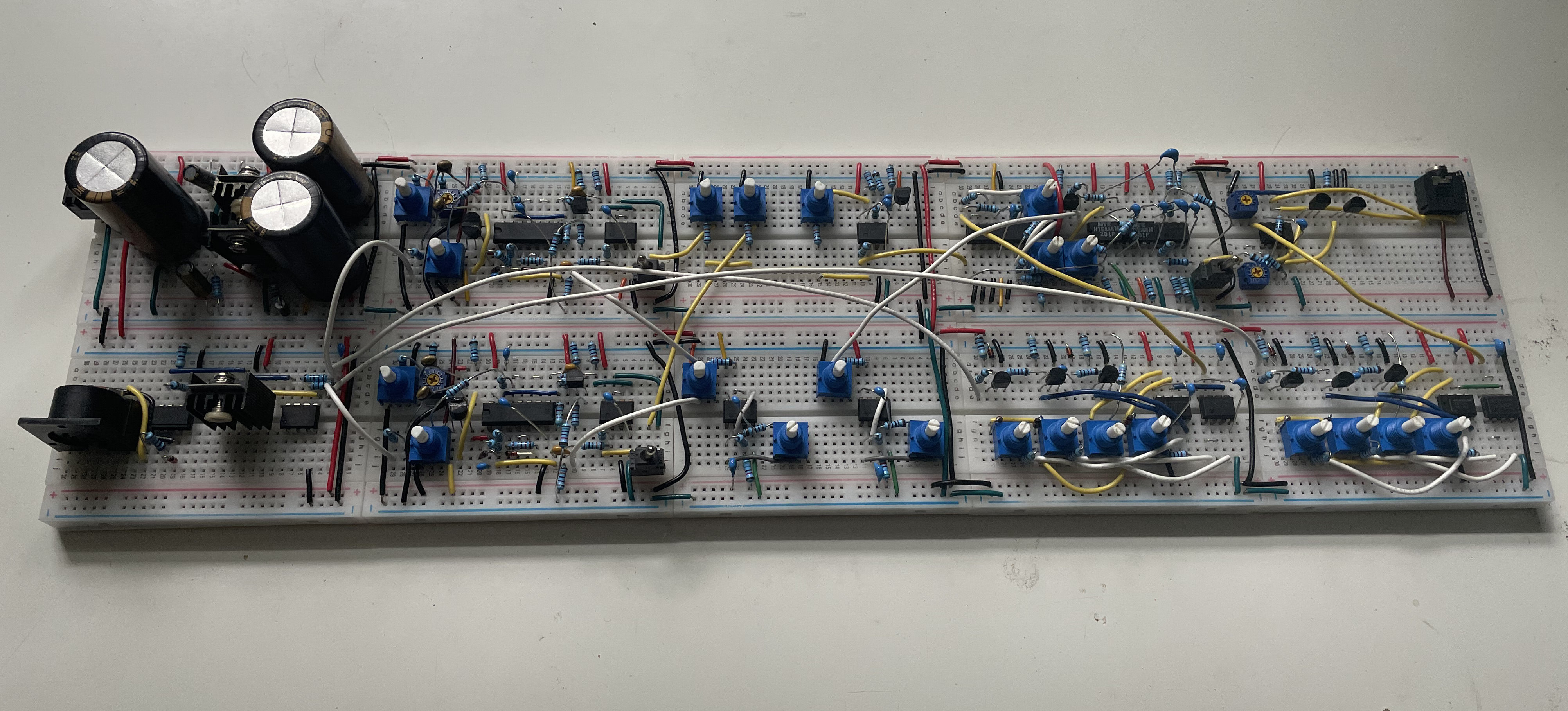
This is BS-1, my breadboard synthesizer. It features a dual-rail power supply, a MIDI-to-CV converter, two oscillators, two LFOs, a noise source, a mixer, a Polivoks VCF clone, two ADSRs, and a VCA. Since I am no analog electronics expert by any means, none of these designs are original, and instead were taken from various places off the Internet. However, I want to write this article to explain how I picked out the designs, and how the build process went overall.
Rules of the Game
Before I started picking out designs for components, I set up two simple rules to help narrow things down:
- No chips that do everything for me (e.g. CEM3340)
- Each module must fit on a standard 400-terminal breadboard
I didn't want the project to be too easy, but I also did not want to spend 12 hours straight building a filter. These rules helped me meet that goal.
VCOs
For the oscillators, I chose the VCO 4069 design by René Schmitz:
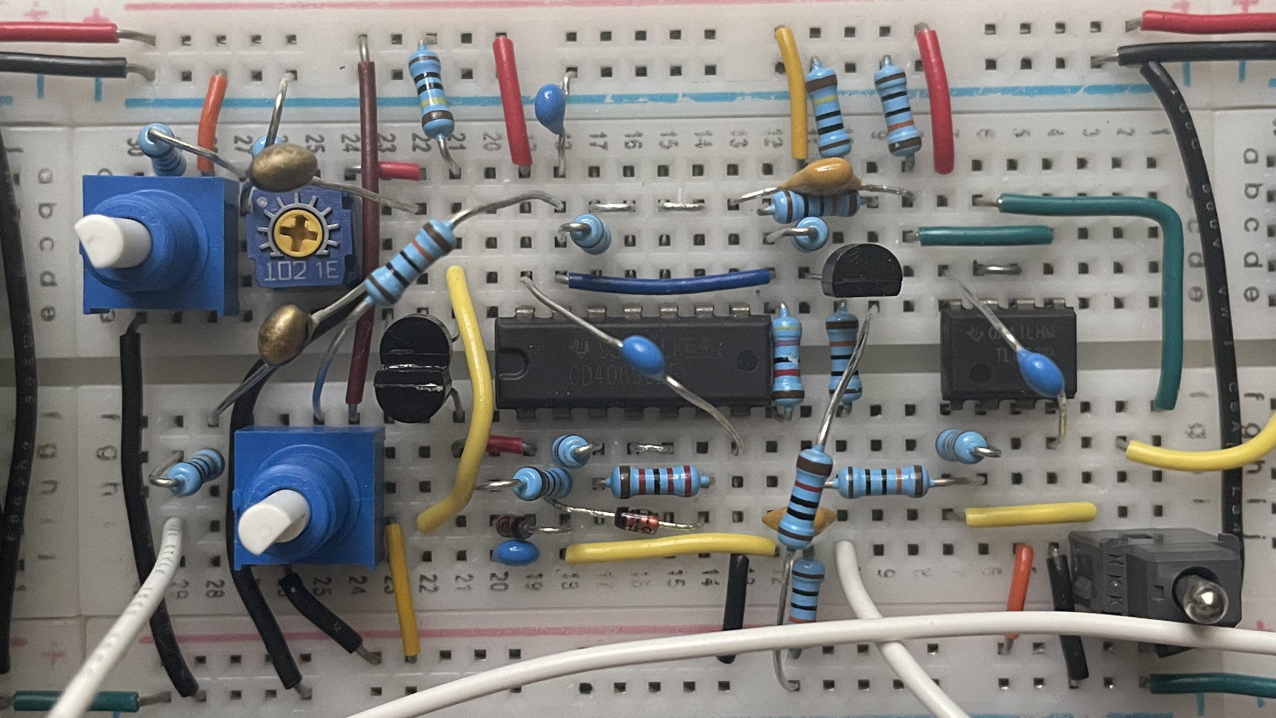
A genuis design based around the 4069 CMOS Hex Inverter, it provides both a saw and a PWM output.
Rationale
I was really attracted to the use of an inverter chip to create an oscillator, as to someone like me who is a relative beginner with analog electronics, it seems so esoteric. Generally, I would expect an inverter to be used in some digital circuit, not an analog waveform generator! I also liked the simplicity of the circuit, since that way it would fit on the single breadboard I wanted it on. Finally, PWM was a requirement to me, so I was happy to find out that simple circuits like this one could provide it.
Construction Notes
Fitting this circuit on the single breadboard was a little tricky, especially the core saw wave part, which you can see at the bottom side of the 4069. More annoyingly, though, I ran into an issue where the circuit would generate some sort of buzzing on the power rails. After I had built the VCF, I found that even with the oscillator fully detached, a buzz would still come into the filter. I ended up solving this by touching my pliers to random parts of the circuit, ultimately finding that when I touched pin 13 of the 4069, the buzz would go away. Knowing that my pliers were introducing some sort of capacitance, I put a small ceramic capacitor between pin 13 and ground, and the buzz went away. If anyone can actually explain what was happening, I would definitely appreciate it!
Caveats
I found that the PWM control was a bit strange, and 50% on the potentiometer does not actually correspond to 50% pulse width. Given that I built this circuit twice, I don't think I made an error in construction, and I guess that's just how it is.
LFOs
To get a little modulation going, I built two simple op-amp relaxation LFOs:
These are hardwired to the PWM input of each oscillator and the filter cutoff. Not much to say about these since it is such a simple circuit. I cannot even remember the exact website I got it off of as it is so ubiquitous.
Mixer + Noise Source
Another simple circuit: just a 3-channel summing mixer with a transistor breakdown white noise source:
This mixes together both of the oscillators and adds a little texture with the white noise before going off to the VCF.
Construction Notes
The transistor noise was actually a little tricky to nail down. Most example schematics for the most minimal design use a common emitter amplifier to bring up the noise. However, I wanted to use an op-amp so that I could use a dual op-amp chip and combine it with the mixer. While making an amplifier with an op-amp is easy, it took me a while to realize that I needed to amplify way more than I thought I would have to. I forget what gain I ultimately set it to, but it is still too low, and at this point I am too lazy to fix it. Not sure if that issue comes down to not using the right value resistor on the transistor, or if I really just need to set the gain higher.
VCF
Here is the real star of the show, the Polivoks VCF clone:
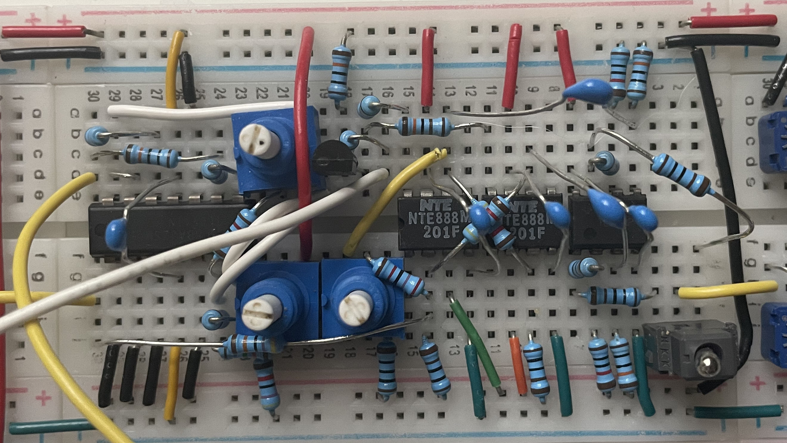
This design comes from Dave Brown, which in turn is a modified version of Marc Bareille's design, using NTE888M op-amps as a replacement for the original Soviet ones.
Rationale
Picking out a VCF was really hard. Most people seem to either recommend a full-on Moog filter or the absolute bare minimum op-amp thingy. However, I wanted something between those two. After looking all over the place, I came across this genius design. Ordering the NTE888Ms was a bit annoying, but in the end it was worth it.
Construction Notes
I ended up cutting out a couple features from the design due to limited space on the breadboard. First off, I removed the 1V/oct FM input, which I did not really mind that much since I did not intend to patch pitch CV into the filter anyway. Secondly, I had to remove the switch between hard and soft clipping in the filter, which is a bit of a shame when doing self-oscillation. It would be nice to have a less aggressive mode, but I guess that could come in a future synthesizer.
ADSRs
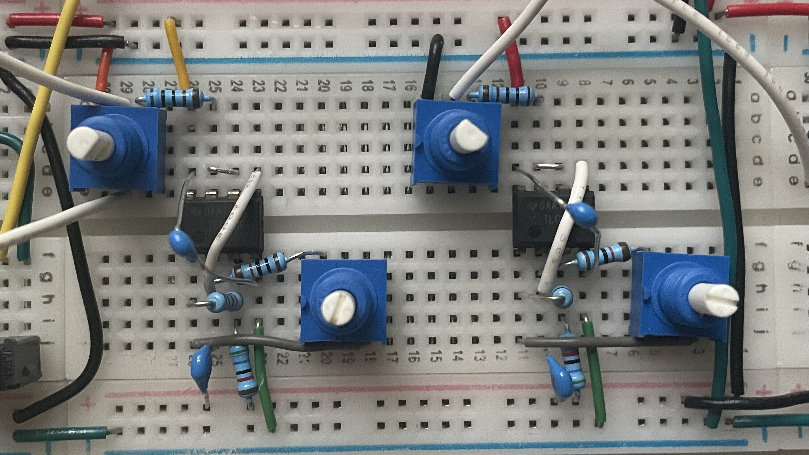
I built two ADSR envelope generators using René Schmitz's Fastest ADSR in the West design:
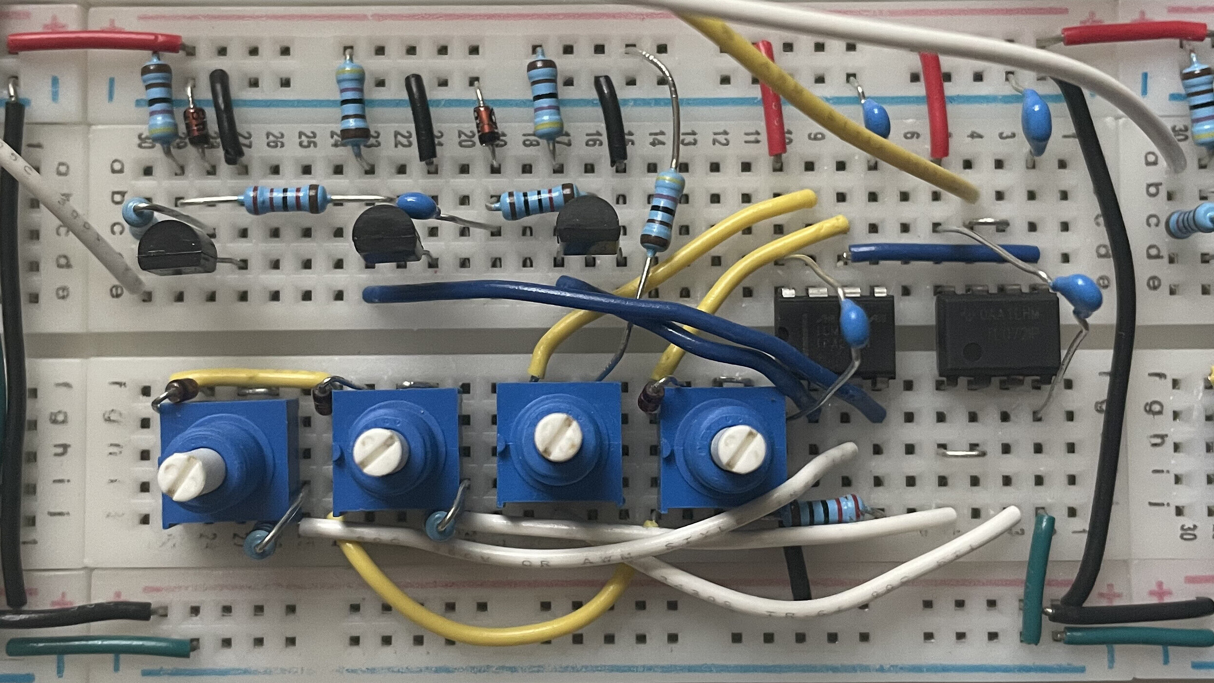
One is wired to the cutoff of the VCF, and the other is wired to the amplitude of the VCA.
Construction Notes
Squeezing these onto the breadboards was extremely difficult. While the circuit to generate the trigger pulse breadboarded very well, the rest was a total mess. It took two tries to really get it right, as on the first try, diodes were crossing everywhere, nearly shorting out. Luckily, I was able to figure out a much better layout, and now it is fairly neat.
Caveats
For some reason, even with the release set all the way down, the output does not fully shut off, and instead gets very low and then tapers off towards zero very slowly. This could be a construction error, as I had a bit of a hard time reading the capacitor values in the hand-drawn schematic. However, it could also just be a flaw of the design.
VCA
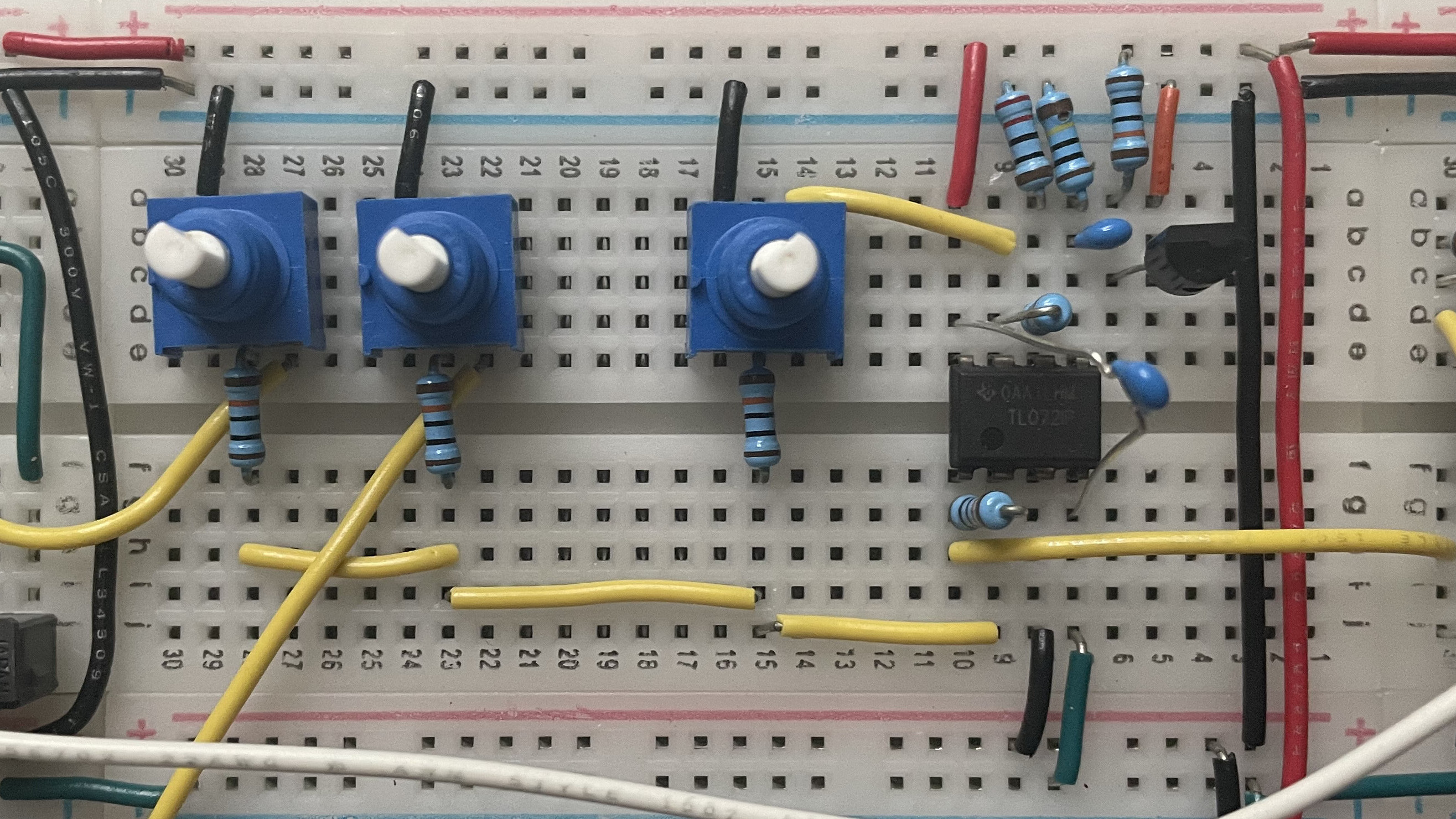
To complete the main signal chain, we have a VCA using Henry Santana's dual JFET design:
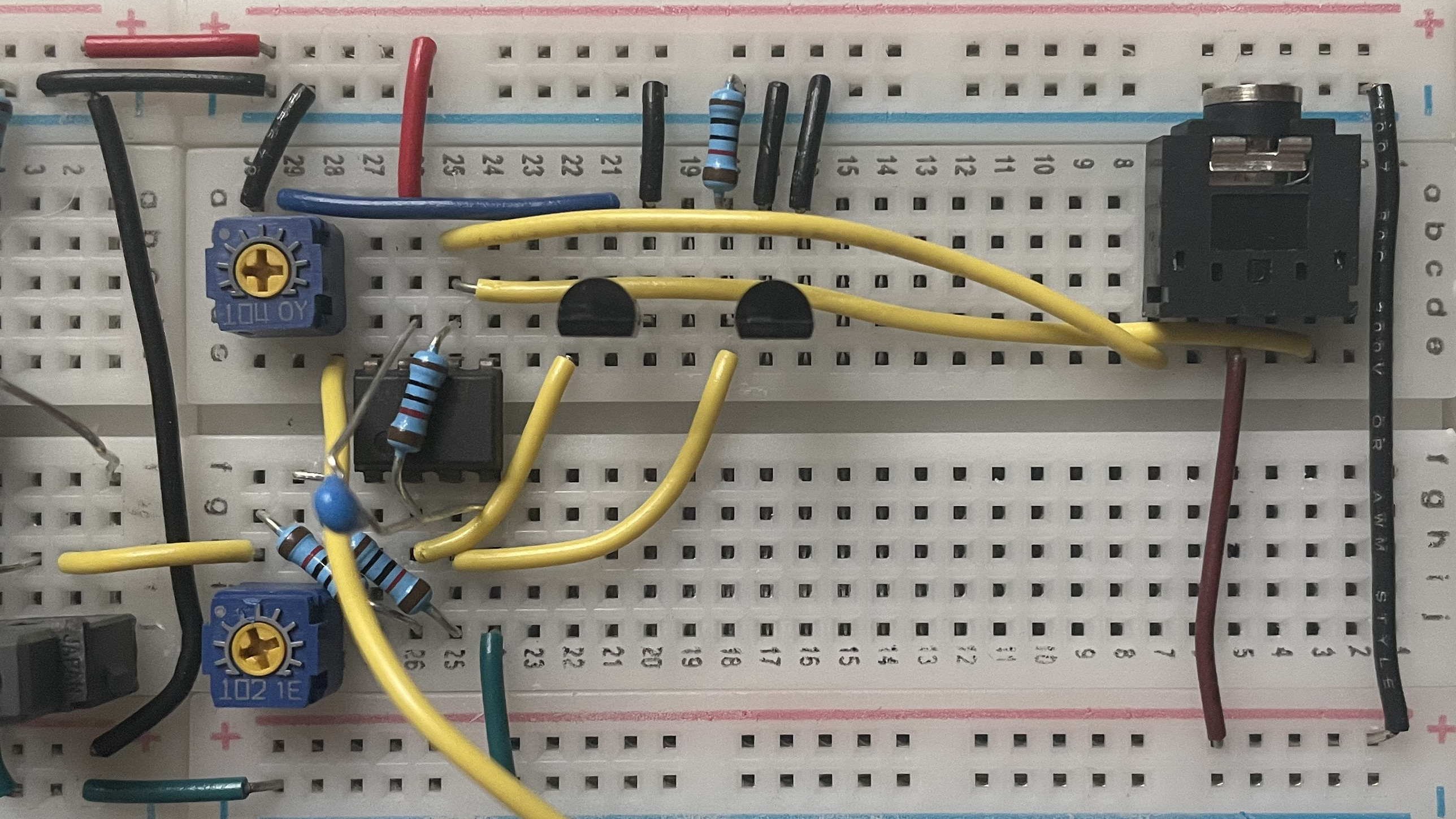
Originally published in Electronic Design Magazine, this design is about as simple as it gets, requiring only two JFETs, an op-amp, and a couple resistors.
Rationale
Most people online seem to recommend using a VCA chip such as the THAT2180, but would go against my rules for the project. It took a lot of searching, but I eventually came across this design, which performs amazingly well for how simple it is. It does require matched JFETs, but unlike what some people seem to claim, they do not need to be perfectly matched, and slight differences can be accounted for with a trimpot.
The Rest
Lastly, there are two more components that I have not touched on yet: the power supply and the MIDI-to-CV converter. The power supply is the Goldpoint VG-1 circuit, featuring some massive capacitors for smoothing. The MIDI-to-CV converter is based around Jan Ostman's Good Ol' MIDI to CV project. I made some slight modifications to the code as it handles stacked notes really strangely by default. For now I am going to leave those modifications private out of sheer laziness, but if anyone wants to see them, feel free to reach out and I can publish them.
Demo Video
Here is a quick video showing off some features of BS-1:
Conclusion
In the end, I could not be happier with how this project turned out and how much I learned from it. I honestly did not expect to even be able to make it this far, as I have nearly no background in analog electronics. Though most of the project was glueing together existing designs, it still took a lot of effort and research to figure out which designs to use, how exactly to combine them, and how to modify them to fit my goals. I am thinking about how I could build another synthesizer, though I have no idea what it would look like yet. Maybe something more Buchla inspired?
As a final note, I will be releasing a full song made exclusively with BS-1 at Flashparty 2021. After that, the song will be available for download on my Bandcamp.